<?xml version="1.0" encoding="utf-8"?><feed xmlns="http://www.w3.org/2005/Atom" ><generator uri="https://jekyllrb.com/" version="4.4.1">Jekyll</generator><link href="https://blog-713f1f.git-pages.tuwien.ac.at//blog/feed.xml" rel="self" type="application/atom+xml" /><link href="https://blog-713f1f.git-pages.tuwien.ac.at//blog/" rel="alternate" type="text/html" /><updated>2026-03-19T13:23:48+00:00</updated><id>https://blog-713f1f.git-pages.tuwien.ac.at//blog/feed.xml</id><title type="html">Scuderia Segfault Blog</title><subtitle>On this blog write about the small and the little things we are working on. Most of the content in this blog is still experimental and should be used on your own risk, but some things might help you win races!</subtitle><entry><title type="html">Radio Controller</title><link href="https://blog-713f1f.git-pages.tuwien.ac.at//blog/2026/03/17/radio-controller.html" rel="alternate" type="text/html" title="Radio Controller" /><published>2026-03-17T00:00:00+00:00</published><updated>2026-03-17T00:00:00+00:00</updated><id>https://blog-713f1f.git-pages.tuwien.ac.at//blog/2026/03/17/radio-controller</id><content type="html" xml:base="https://blog-713f1f.git-pages.tuwien.ac.at//blog/2026/03/17/radio-controller.html"><![CDATA[<p>This project provides all the information on our new radio controllers for the RoboRacer racecars. They have much better connection to the car and allow for greater customization than the old Logitech gamepads. <!--more-->
A rough structure of the project is:</p>

<p>Radiomaster Pocket ELRS 2.4GHz Controller &lt;– ELRS Protocol –&gt; any 2.4GHz ELRS Receiver (currently: Happymodel EP1 Nano) &lt;– UART –&gt; STM32F103C8 (aka Bluepill) &lt;– male micro USB to male USB-A cable –&gt; PC (car, laptop)</p>

<h2 id="general-use">General Use</h2>

<ul>
  <li>Install the gimbal sticks by screwing them into the gimbals. Remove them when storing the controller to protect the gimbals and keep the sticks at the back of the controller in their slots.</li>
  <li>Power-on the remote by pressing the power button until the four squares are displayed and the controller rumbles.</li>
  <li>Clear the throttle and button warnings by moving the left gimbal down and resetting all the buttons to be off.</li>
  <li>If the STM32F103C8 is connected and the paired receiver is powered up, the remote connects automatically. It also reconnects automatically after loosing connection (both is announced by the controller with a voice-line).  The receiver indicates its looking for a connection by slow-blinking of its green LED. When it is connected the LED is on continuously.</li>
  <li>If the receiver is turned on and no remote connects to it within 60 seconds, it switches into config mode: the green LED will blink rapidly and it starts a WIFI network, which can be used to update its firmware. Power the receiver down and back up to for it to look for connections to the remote. Once the receiver was connected to a controller, if it loses connection, it will not go into configuration mode (even after more than 60 seconds have passed), but keep looking to reconnect to the controller.</li>
  <li>The currently used buttons are as follows
    <ul>
      <li>The left gimbal (yellow) is used to control the vehicle’s speed.</li>
      <li>The right gimbal (pink) is used to control the vehicle’s steering.</li>
      <li>The left shoulder button (blue) is used to put the vehicle into speed mode: the position of the left gimbal then corresponds to the speed of the vehicle. A green LED indicates that this button is active.</li>
      <li>The right shoulder button (green) is used to put the vehicle into acceleration mode: the position of the left gimbal then corresponds to the acceleration of the vehicle (going backwards is not possible in this mode). A green LED indicates that this button is active.</li>
      <li>The back left momentary switch (red) is the deadman switch for autonomous driving: as long as this switch is held down, the algorithm will drive the car autonomously.</li>
    </ul>
  </li>
</ul>

<p><img src="/blog/assets/radio_controller/radiomaster_explanation.jpg" alt="Explanation of used buttons on the RadioMaster Pocket controller" /></p>

<ul>
  <li>The control can be charged via the USB-C port <strong>on the bottom</strong>. The USB-C port on the top is to use the controller as a joystick on a PC (for example, as wired connection to train in flight sims). <strong>Never connect both USB-C ports simultaneously, this will break the controller!</strong></li>
  <li>Power-off the remote by pressing and holding the power button until the squares on the display disappear. If the receiver is connected, you will receive a warning which you have to clear by pressing enter via the scroll wheel below the right gimbal.</li>
  <li>The <code class="language-plaintext highlighter-rouge">SYS</code> button opens the settings, the scroll wheel can then be used to navigate up and down. Use the <code class="language-plaintext highlighter-rouge">page&lt;</code>, <code class="language-plaintext highlighter-rouge">page&gt;</code> buttons to move between menu pages. With a long press of the <code class="language-plaintext highlighter-rouge">RTN</code> button one can return from the menu to the home screen. On the home screen the <code class="language-plaintext highlighter-rouge">page&lt;</code>, <code class="language-plaintext highlighter-rouge">page&gt;</code> buttons allow to change the additional information that can be viewed.</li>
  <li>To switch the transmission power level in case of bad connection
    <ol>
      <li>press the <code class="language-plaintext highlighter-rouge">SYS</code> button</li>
      <li>move into the ExpressLRS menu by clicking the wheel.</li>
      <li>scroll to and select <code class="language-plaintext highlighter-rouge">TX Power</code> from the menu via clicking the wheel.</li>
      <li>select <code class="language-plaintext highlighter-rouge">Max Power</code> via clicking the wheel and scrolling to select the desired output power, click again to confirm it</li>
      <li>Press and hold the <code class="language-plaintext highlighter-rouge">RTN</code> button to go back to the home screen</li>
    </ol>
  </li>
</ul>

<h2 id="hardware-overview">Hardware Overview</h2>

<ul>
  <li><a href="https://www.radiomasterrc.com/products/pocket-radio-controller-m2?variant=47236836360423">Radiomaster Pocket ELRS 2.4GHz (LBT) Controller</a>: Chosen for its size and similarity to a gamepad and the momentary shoulder switch, which is ideal for use as a deadman switch. It can also support other protocols (CRSF, FreeSky, etc.), other frequencies (ELRS 915/868MHz) and more output power (up to 1W) via the external nano module bay. Note that the receiver needs to match the protocol and frequency of the transmittor module. We chose ELRS 2.4GHz since this frequency is free to use all over the world.</li>
  <li>2 pieces of <a href="https://www.radiomasterrc.com/products/18650-3200mah-3-7v-battery-2pcs-for-tx16s-boxer-tx12-mt12-radios">18650 batteries</a>: for the controller, can be charged by the controller</li>
  <li>SD-Card: apparently the SD-card coming with the controller (512MB) is unreliable, therefore we switched to SanDisk ones, any reputable brand will do.</li>
  <li><a href="https://www.happymodel.cn/index.php/2021/04/10/happymodel-2-4g-expresslrs-elrs-nano-series-receiver-module-pp-rx-ep1-rx-ep2-rx/">Happymodel EP1 Nano ELRS 2.4GHz Receiver</a>: Any other ELRS 2.4GHz receiver can be chosen. This receives the signal from the controller and sends it via UART to the STM32 microcontroller.</li>
  <li><a href="https://www.st.com/en/microcontrollers-microprocessors/stm32f103c8.html">STM32F103C8 aka Bluepill</a> board: This microcontroller does not seem to be in production anymore, but the clones also do the job and are relatively cheap. It takes the input data from the ELRS receiver via UART and emulates a USB computer joystick (USB HID device). The original repository can be found <a href="https://github.com/cruwaller/rc_receiver_to_usb_hid">here</a> (note that the CRSF firmware has to be used from this repo for some reason).</li>
  <li>Male micro USB to male USB-A data cable: to connect the microcontroller to the PC (car, laptop…).</li>
  <li>Either an ST-Link programmer or an FTDI adapter (FT232RL USB to TTL Serial) in order to flash the firmware onto the STM32 microcontroller</li>
</ul>

<h2 id="initial-setup">Initial Setup</h2>

<h3 id="radiomaster-pocket-controller">Radiomaster Pocket Controller</h3>

<p><img src="/blog/assets/radio_controller/left_gimbal_self_centering.png" alt="Location of screws that need modifications" /></p>

<ol>
  <li>Remove the soft rubber on the back on both sides.</li>
  <li>Make left gimbal self centering (horizontally): with the controller lying on the front, using a 1.5mm hex wrench, on the right side: turn the L-R (red in picture) counter-clockwise (a fair bit, this allows for vertical stick tension) and turn the screw marked with up-down arrows clockwise (blue in picture) also a fair bit (this increases the vertical stick tension).</li>
  <li>Install the batteries in the correct way in the back of the controller.</li>
  <li>Reinstall the soft rubber on the back on both sides.</li>
  <li>If using a new SD-card: the file system must be FAT32 and the <a href="https://www.radiomasterrc.com/pages/firmware-updates">Pocket ELRS firmware</a> must be put on it (all the folders inside the SD-Content and Restore-Default-Settings have to be copied onto the SD-card). Afterwards remove the old SD-card and install the new one at the bottom of the controller.</li>
</ol>

<h3 id="connecting-the-stm32f103c8-to-the-receiver">Connecting the STM32F103C8 to the Receiver</h3>

<p>The table shows the wiring (check the documentation of the receiver for its connector arrangement!):</p>

<table>
  <thead>
    <tr>
      <th>Receiver</th>
      <th>STM32F103C8 (Bluepill)</th>
    </tr>
  </thead>
  <tbody>
    <tr>
      <td>TX</td>
      <td>PA3 (USART2 RX)</td>
    </tr>
    <tr>
      <td>5V</td>
      <td>5V</td>
    </tr>
    <tr>
      <td>GND</td>
      <td>GND</td>
    </tr>
    <tr>
      <td>RX</td>
      <td>currently not connected</td>
    </tr>
  </tbody>
</table>

<p>For the Happymodel EP1 Nano, this is the current wiring:</p>

<p><img src="/blog/assets/radio_controller/happymodel_ep1_to_bluepill_wiring.jpeg" alt="Wiring for the exact components used in this tutorial." /></p>

<h3 id="binding-the-receiver-to-the-controller">Binding the Receiver to the Controller</h3>

<ol>
  <li>Make sure the Controller is turned off</li>
  <li>Disconnect and reconnect the power to the receiver three times (for example by un- and re-plugging the USB to the STM32F103C8). The green LED on the receiver should start to blink twice and pause to indicate pairing mode.</li>
  <li>Turn the controller on by long pressing the power button until all four squares appear on the screen and the controller rumbles for a short period. If met with a throttle/button warning, turn the left gimbal to the bottom and set all buttons to their off-state (the two three-position switches must be in the back-position).</li>
  <li>Press the SYS button to get to the TOOLS page.</li>
  <li>Press the wheel below the right-gimbal to enter the ExpressLRS menu.</li>
  <li>Using the wheel, scroll to the <code class="language-plaintext highlighter-rouge">[Bind]</code> option and press the wheel to select it.</li>
  <li>The green LED on the receiver should stop to double-blink and light up continuously to indicate that it is connected to the remote.</li>
  <li>You can leave the menu by long-pressing the RTN button.</li>
</ol>

<h3 id="flashing-the-binaries-to-the-stm32f103c8">Flashing the Binaries to the STM32F103C8</h3>

<ul>
  <li>The binaries can be downloaded from releases</li>
  <li>To connect the hardware used to flash the STM32F103C8, look up a tutorial, as this step depends on your flashing hardware (FTDI tutorial: use this to flash our binaries and not the maple bootloader as they do in their tutorial)</li>
</ul>

<h4 id="using-st-link">Using ST-LINK</h4>

<p><img src="/blog/assets/radio_controller/STM32-Operating-and-Programming-Mode.jpg" alt="Jumper positions for programming and operating mode." /></p>

<ol>
  <li>
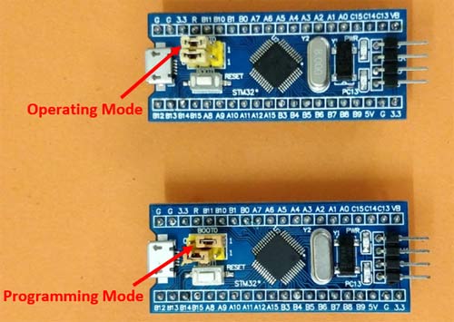
Put the STM32F103C8 in programming mode: move the BOOT0 jumper to the 1 position (see picture above).</li>
  <li>
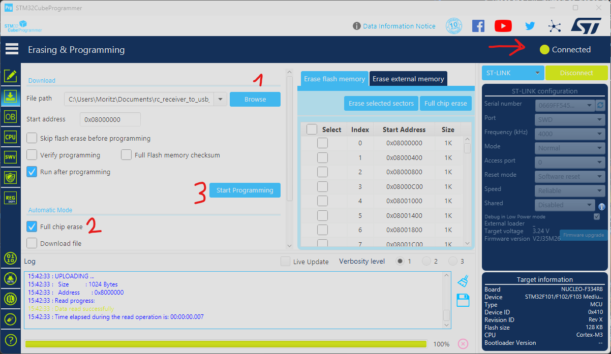
Install STM32CubeProgrammer</li>
  <li>Connect the ST-Link programmer (which you already connected with the help of a tutorial to the STM32F103C8) to your PC.</li>
  <li>In the <a href="https://www.st.com/en/development-tools/stm32cubeprog.html">STM32CubeProgrammer</a> make sure the STM32 is connected, select the firmware file, select full chip erase and start programming the board (refer to screenshot below).</li>
  <li>Put the STM32F103C8 in operating mode: move the BOOT0 jumper back to the 0 position (see picture from step 1).</li>
</ol>

<p><img src="/blog/assets/radio_controller/stlink_programming.png" alt="Screenshot of STM32CubeProgrammer to flash the firmware on the chip." /></p>

<h4 id="using-an-ftdi-adapter">Using an FTDI adapter</h4>

<ol>
  <li>Put the STM32F103C8 in programming mode: move the BOOT0 jumper to the 1 position (see picture at Using ST-LINK, step 1 above).</li>
  <li>Install <a href="https://www.st.com/en/development-tools/flasher-stm32.html#get-software">STM32 Flash Loader Demonstrator</a></li>
  <li>Connect the FTDI adapter (which you already connected with the help of a tutorial to the STM32F103C8) to your PC.</li>
  <li>
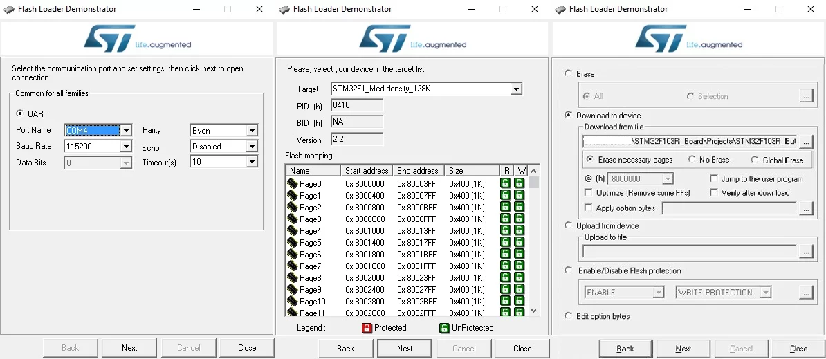
Start the ‘Flash Loader Demonstrator’</li>
  <li>Select the port of the FTDI adapter and click next.</li>
  <li>The device in the target list should be correct, check it and click next.</li>
  <li>Click ‘Download to Device’, choose our firmware binaries in the ‘Download from file’ textbox, check ‘Erase necessary pages’ and click next.</li>
  <li>After successfully flashing, put the STM32F103C8 back into operating mode: move the BOOT0 jumper back to the 0 position (see picture at Using ST-LINK, step 1 above).</li>
</ol>

<p><img src="/blog/assets/radio_controller/flash_loader_demonstrator.png" alt="Screenshot of STM32CubeProgrammer to flash the firmware on the chip." /></p>

<h3 id="testing-the-functionality">Testing the Functionality</h3>

<p>To test the functionality of the controller:</p>

<ol>
  <li>Turn on the controller</li>
  <li>Connect the STM32F103C8 to the PC via a micro-USB B to A cable.</li>
  <li>open a testing program: Linux users can use jstest-gtk, Windows users can use the setup game controllerfunction.</li>
  <li>If nothing moves: make sure the controller is connected to the receiver and the STM32F103C8 is in operating mode and push the reset button.</li>
</ol>

<h2 id="development">Development</h2>

<p>The original code is from <a href="https://github.com/cruwaller/rc_receiver_to_usb_hid">here</a>. Platformio is used to develop, its a VSCode extension and very easy to install. The current configuration of the STM32F103C8 is:</p>

<ul>
  <li>4 analog channels (0…2047)</li>
  <li>8 buttons (binary) With the Radiomaster Pocket we currently can use all 4 analog channels and 6 of the buttons (one of them being the wheel at the back).</li>
</ul>

<h3 id="debugging">Debugging</h3>

<p>Debugging can be enabled by commenting out the options in the platformio.ini file. However, debugging requires an ST-Link programmer connected to the STM32F103C8.</p>]]></content><author><name>[&quot;Moritz Christamentl &lt;moritz.christamentl@tuwien.ac.at&gt;&quot;, &quot;Felix Resch &lt;felix.resch@tuwien.ac.at&gt;&quot;]</name></author><summary type="html"><![CDATA[This project provides all the information on our new radio controllers for the RoboRacer racecars. They have much better connection to the car and allow for greater customization than the old Logitech gamepads.]]></summary></entry><entry><title type="html">Track2Vehicle Module</title><link href="https://blog-713f1f.git-pages.tuwien.ac.at//blog/2026/03/17/t2v-module.html" rel="alternate" type="text/html" title="Track2Vehicle Module" /><published>2026-03-17T00:00:00+00:00</published><updated>2026-03-17T00:00:00+00:00</updated><id>https://blog-713f1f.git-pages.tuwien.ac.at//blog/2026/03/17/t2v-module</id><content type="html" xml:base="https://blog-713f1f.git-pages.tuwien.ac.at//blog/2026/03/17/t2v-module.html"><![CDATA[<p>One issue we have encountered in the many races we have participated in is the impact of human reaction time during the
starting sequence.
<!--more-->
While a difference in starting time might have been a minor annoyance a few years ago, today we have incredibly
competitive teams with lap times only separated by a few hundredths of a second. With such a minor difference in lap times,
the result of the race may come down to human reaction time, which is in the order of a few tenths of a second.</p>

<p>As a mitigation for this problem, we are pleased to announce the new RoboRacer Track to Vehicle Module (T2V Module),
developed in cooperation with the RoboRacer foundation for the 27th RoboRacer Grand Prix in Vienna. The T2V Module
consists of one or more transmitters located around the track, which send commands and track information to receivers
mounted on the cars using infrared signals. During the Vienna Grand Prix, we will utilize this system to start the races
and, if possible, to indicate slow-driving sections<sup id="fnref:1"><a href="#fn:1" class="footnote" rel="footnote" role="doc-noteref">1</a></sup>.</p>

<p>To allow for an early roll-out to as many teams as possible, we provide build instructions and software for the
receivers, based on the ESP32-P4 platform. Teams can find those instructions on GitHub in the repository for the T2V
Module. We also provide a basic ROS integration and will include a sensible integration for our Ackermann Mux NG (our new implementation for the Ackermann Mux, which we will release soon). All instructions, source code, and designs will be available as open-source projects under MIT or CC0 licenses, respectively, after we have finalized the initial versions for each component.</p>

<h2 id="the-protocol">The protocol</h2>

<p>The T2V Module uses IR NEC<sup id="fnref:2"><a href="#fn:2" class="footnote" rel="footnote" role="doc-noteref">2</a></sup> frames to relay information from the track to the cars. Many commercially available
infrared remotes use IR NEC frames to transmit data, and the protocol is simple enough for small microcontrollers to
interpret. One drawback of the protocol is that it is comparatively slow, with one frame requiring approximately 67.5 ms
to transmit. While this is not an issue if all cars use the T2V Module, the starting system has to take the frame
transmission time into account when human drivers are involved. The T2V protocol only uses the standard mode for IR NEC
addressing, not the extended variant.</p>

<p>IR NEC transmits an address and a command in each frame, both of which are utilized by the T2V Module. Systems using the T2V
Module protocol MUST use the address to process only frames destined for the system. For this purpose, we define four
blocks of addresses that require different treatment. The table below defines the different blocks of addresses.</p>

<table>
  <thead>
    <tr>
      <th>Start</th>
      <th>End</th>
      <th>Name</th>
    </tr>
  </thead>
  <tbody>
    <tr>
      <td><code class="language-plaintext highlighter-rouge">00</code></td>
      <td><code class="language-plaintext highlighter-rouge">0F</code></td>
      <td>Multicast</td>
    </tr>
    <tr>
      <td><code class="language-plaintext highlighter-rouge">10</code></td>
      <td><code class="language-plaintext highlighter-rouge">7F</code></td>
      <td>Race reserved</td>
    </tr>
    <tr>
      <td><code class="language-plaintext highlighter-rouge">80</code></td>
      <td><code class="language-plaintext highlighter-rouge">EF</code></td>
      <td>Open addresses</td>
    </tr>
    <tr>
      <td><code class="language-plaintext highlighter-rouge">F0</code></td>
      <td><code class="language-plaintext highlighter-rouge">FE</code></td>
      <td>RFU (Reserved for future use)</td>
    </tr>
    <tr>
      <td><code class="language-plaintext highlighter-rouge">FF</code></td>
      <td><code class="language-plaintext highlighter-rouge">FF</code></td>
      <td>Broadcast</td>
    </tr>
  </tbody>
</table>

<p>We use <strong>multicast</strong> (<code class="language-plaintext highlighter-rouge">0x00</code> - <code class="language-plaintext highlighter-rouge">0x0F</code>) addresses to identify a group of receivers that MUST process a frame, such as all
cars on one track or all cars in a group (e.g. all cars from the same team, or all cars in a training slot). To address
all receivers at once, we define the <strong>broadcast</strong> address (<code class="language-plaintext highlighter-rouge">0xFF</code>).
Any receiver receiving a frame with this address MUST process the frame.</p>

<p>For organizational reasons, we split the unicast addresses into two ranges: the <strong>race reserved</strong> (<code class="language-plaintext highlighter-rouge">0x10</code> - <code class="language-plaintext highlighter-rouge">0x7F</code>)
range and the open (<code class="language-plaintext highlighter-rouge">0x80</code> - <code class="language-plaintext highlighter-rouge">0xEF</code>) range. During a race, the race directors assign <strong>race reserved</strong> addresses. No
receiver SHALL use an address in this range unless the race directors have assigned it. Receivers can use any <strong>open</strong>
address freely at any time, but teams SHOULD coordinate the used addresses during a race. Addresses in the range
<code class="language-plaintext highlighter-rouge">0xF0</code> - <code class="language-plaintext highlighter-rouge">0xFE</code> are <strong>reserved for future use</strong>.</p>

<p>To date, only the essential commands required for a starting system have been defined. After the Vienna Grand Prix, we
will develop a standardization process to add additional commands to the standard. A complying device needs to implement
at least the commands <code class="language-plaintext highlighter-rouge">START_GO</code>, <code class="language-plaintext highlighter-rouge">START_ABORT</code>, and <code class="language-plaintext highlighter-rouge">STOP</code>. The other commands, <code class="language-plaintext highlighter-rouge">START_READY</code> and <code class="language-plaintext highlighter-rouge">START_SET</code>, are
informative, and devices might use them to optimize their starting routine (e.g., by allowing the car’s operator to press
the dead man’s switch without the car starting to drive).</p>

<table>
  <thead>
    <tr>
      <th>ID</th>
      <th>Name</th>
      <th>Required</th>
      <th>Usage</th>
    </tr>
  </thead>
  <tbody>
    <tr>
      <td><code class="language-plaintext highlighter-rouge">00</code></td>
      <td>START_READY</td>
      <td>No</td>
      <td>Starting sequence has started.</td>
    </tr>
    <tr>
      <td><code class="language-plaintext highlighter-rouge">01</code></td>
      <td>START_SET</td>
      <td>No</td>
      <td>Start of race is imminent.</td>
    </tr>
    <tr>
      <td><code class="language-plaintext highlighter-rouge">02</code></td>
      <td>START_GO</td>
      <td>Yes</td>
      <td>Start the race.</td>
    </tr>
    <tr>
      <td><code class="language-plaintext highlighter-rouge">03</code></td>
      <td>START_ABORT</td>
      <td>Yes</td>
      <td>Start sequence has been aborted.</td>
    </tr>
    <tr>
      <td><code class="language-plaintext highlighter-rouge">04</code> - <code class="language-plaintext highlighter-rouge">7E</code></td>
      <td>—</td>
      <td> </td>
      <td>RFU</td>
    </tr>
    <tr>
      <td><code class="language-plaintext highlighter-rouge">7F</code></td>
      <td>STOP</td>
      <td>Yes</td>
      <td>The car MUST stop immediately.</td>
    </tr>
    <tr>
      <td><code class="language-plaintext highlighter-rouge">80</code> - <code class="language-plaintext highlighter-rouge">FF</code></td>
      <td>—</td>
      <td> </td>
      <td>RFU</td>
    </tr>
  </tbody>
</table>

<h2 id="reference-receiver">Reference Receiver</h2>

<p>We aim to make the T2V Module accessible to as many teams as possible by providing an affordable and widely available
Reference Receiver. To achieve this, we have based the receiver on
the <a href="https://www.waveshare.com/esp32-p4-nano.htm">ESP32-P4-NANO</a> from Waveshare, which is internationally available and
costs less than 20 USD. In the minimum configuration, teams need to purchase an additional IR Receiver, a USB plug with
a corresponding cable, and a few jumper wires. We also provide a PCB design that includes the USB plug, headers for the
IR receiver, and headers for some typical low-level protocols, such as I2C, SPI, and one-wire. We will release the build
instructions in a forthcoming post, followed by the PCB design once it has been finalized and tested.</p>

<p>The firmware handles the processing of the IR NEC frames and communication as a USB device. As we intend to expand the
receiver’s functionality to read data from temperature sensors and voltage meters, these features will also be generally
available when we have finished testing them.</p>

<p>The Reference Receiver uses USB Full-Speed to transfer the IR NEC frames to the car. By default, it uses the vendor ID
<code class="language-plaintext highlighter-rouge">0x5455</code>, the product ID <code class="language-plaintext highlighter-rouge">0x1911</code> and a vendor-specific interface with one endpoint. The endpoint with ID 1 is
an IN Interrupt endpoint that transfers 4 bytes of data (the IR NEC frame) when a frame is received.
For details on extensions and their endpoints, please refer to the documentation on the extension-specific branches.</p>

<p>For configuration, the Reference Receiver uses a Bluetooth Low Energy Interface. The race directors use this interface
during races to configure the correct addressing. For this purpose, the device provides a BLE GATT service under the
UUID <code class="language-plaintext highlighter-rouge">c902d400-1809-2a94-904d-af5cbdcefe9b</code> with the required characteristics to properly configure the receiver. The
table below describes the characteristics and their BLE attributes.</p>

<table>
  <thead>
    <tr>
      <th>Characteristic</th>
      <th>Name</th>
      <th>Attributes</th>
      <th>Description</th>
    </tr>
  </thead>
  <tbody>
    <tr>
      <td><code class="language-plaintext highlighter-rouge">FF01</code></td>
      <td>Team Name</td>
      <td>Read-only</td>
      <td>The name of the team.</td>
    </tr>
    <tr>
      <td><code class="language-plaintext highlighter-rouge">FF02</code></td>
      <td>Car Name</td>
      <td>Read-only</td>
      <td>Identfier of the car.</td>
    </tr>
    <tr>
      <td><code class="language-plaintext highlighter-rouge">FF03</code></td>
      <td>IR NEC frames</td>
      <td>Read/Notify</td>
      <td>On read returns the latest IR NEC frame. If used with notifications sends the most recent frame.</td>
    </tr>
    <tr>
      <td><code class="language-plaintext highlighter-rouge">FF04</code></td>
      <td>Unicast address</td>
      <td>Read/Write</td>
      <td>Unicast address for this device.</td>
    </tr>
    <tr>
      <td><code class="language-plaintext highlighter-rouge">FF05</code></td>
      <td>Multicast mask</td>
      <td>Read/Write</td>
      <td>Multicast mask, with each bit in the mask representing one possible address.</td>
    </tr>
  </tbody>
</table>

<h3 id="test-app">Test App</h3>

<p>You can test and configure your reference receiver with the app below.
This app requires a Chromium-based browser with the WebBluetooth API enabled (enable this feature:
<code class="language-plaintext highlighter-rouge">chrome://flags/#enable-experimental-web-platform-features</code>) and a bluetooth adapter on the host device.</p>

<iframe src="/apps/ir_nec/" width="100%" height="500px"></iframe>

<h1 id="reference-sender">Reference Sender</h1>

<p>Similar to the Reference Receiver, we have also developed a Reference Sender for use at the Vienna Grand Prix. It is based
on the same hardware platform as the receiver, but uses Power over Ethernet for power supply and network connectivity.
In the first version, it will allow direct commands via UDP and TCP, as well as communication based on Zenoh for
integration into more complex systems. Once we have finalized the protocols, we will make them available, including some
basic tools for testing.</p>

<h2 id="specialized-sender-starting-lights">Specialized Sender: Starting Lights</h2>

<p><img src="/blog/assets/t2v_module/t2v_start_module.png" alt="Render of a draft of starting lights." /></p>

<p>We drew inspiration from the starting lights used in a slightly larger racing series (hint: about ten times larger) when
designing the starting lights. They feature IR senders, as well as five lamps on each side of the starting line to
indicate the starting process to humans. As mentioned before, the transmission of the IR NEC frame will
finish when the starting lights indicate the start of the race.</p>

<p>We propose the following sequence for the starting lights:</p>

<ol>
  <li>All lights start dark.</li>
  <li>The first light shows red, IR NEC <code class="language-plaintext highlighter-rouge">START_READY</code> is sent.</li>
  <li>Each second, another light turns red until all lights are red.</li>
  <li>IR NEC <code class="language-plaintext highlighter-rouge">START_SET</code> is sent.</li>
  <li>After another second, all lights turn green, IR NEC <code class="language-plaintext highlighter-rouge">START_GO</code> is sent.</li>
</ol>

<p>If the race directors need to abort the start, the lights will flash yellow slowly, and IR NEC <code class="language-plaintext highlighter-rouge">START_ABORT</code> is sent. To
indicate a faulty start, the lights will flash red, and an IR NEC <code class="language-plaintext highlighter-rouge">STOP</code> is sent.</p>
<div class="footnotes" role="doc-endnotes">
  <ol>
    <li id="fn:1">
      <p>Subject to final rule agreement and roll-out of T2V Module. <a href="#fnref:1" class="reversefootnote" role="doc-backlink">&#8617;</a></p>
    </li>
    <li id="fn:2">
      <p>See <a href="https://www.sbprojects.net/knowledge/ir/nec.php">https://www.sbprojects.net/knowledge/ir/nec.php</a> for more details on the IR NEC protocol. <a href="#fnref:2" class="reversefootnote" role="doc-backlink">&#8617;</a></p>
    </li>
  </ol>
</div>]]></content><author><name>Felix Resch &lt;felix.resch@tuwien.ac.at&gt;</name></author><summary type="html"><![CDATA[One issue we have encountered in the many races we have participated in is the impact of human reaction time during the starting sequence.]]></summary></entry></feed>